Keeping the Lights On
Electronic circuits are a major part of our everyday lives whether we are conscious of it or not. Alarm systems, computers, diagnostic medical equipment, Christmas lights, and even a clothes dryer all use logical circuit systems. The truth tables that we've been studying in this chapter actually have a direct use in designing these circuits. Let's take a look at how they correspond.
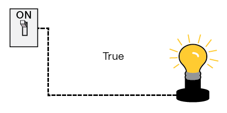
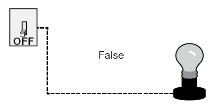
Recall that each variable in a truth table can either be true or false at any given time, but not both at the same time. The same is true of a switch. It can either be on or off, but not both, at any given time. In a digital circuit we associate true with on and false with off.
For instance, if we have a circuit variable that controls a light bulb, when the variable is true, the light is on, and vice versa, as shown in the following diagrams.
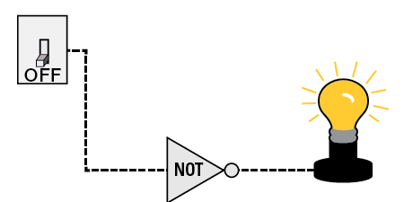
Just as in truth tables, digital circuits can be constructed using logic. The logical connectives for digital circuits are called logic gates. We can add NOT gates, OR gates, or AND gates to any circuit to manipulate the output. As you might imagine, the NOT gate produces an opposite value of the switch as its output. In fact, all the logic gates behave in exactly the same manner as logic symbols in truth tables. For example, suppose we'd like the light to be on when the switch is actually off (or false). We can add a NOT gate to our circuit so the output means the light is on when the switch is off, as shown below.
-
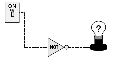
What would happen to the light bulb in this circuit if the switch is on?
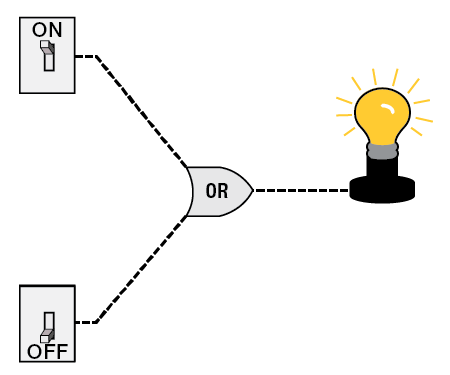
When we have two switches, we can introduce the OR gate so that the light bulb is on if at least one switch is on.
A circuit with two switches leading to an Or gate. The first switch is set to ON. The second switch is set to OFF and leads to a Not gate. The lightbulb is on.
Notice that if we reverse the position of each switch, the light bulb would still remain on. The same is true if both switches are on. However, if both switches were in the off position in this circuit, the light bulb would then turn off.
-
Now think about what would happen to the light bulb with a circuit where there is an AND gate in place. Fill in each blank below.
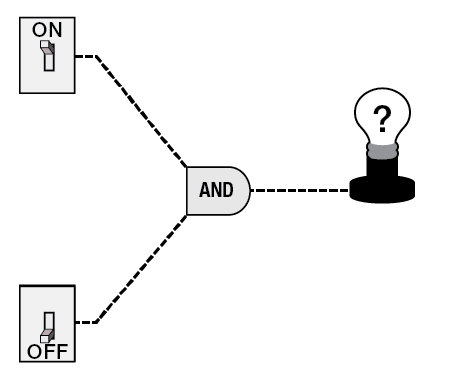
A circuit with two switches leading to an And gate. The first switch is set to ON and the second switch is set to OFF. The lightbulb is labeled with a question mark.
-
If one switch is on and one is off, the light bulb is .
-
If both switches are on, the light bulb is .
-
If both switches are off, the light bulb is .
-
Of course digital circuits can have multiple gates as well as switches, like the one shown below.
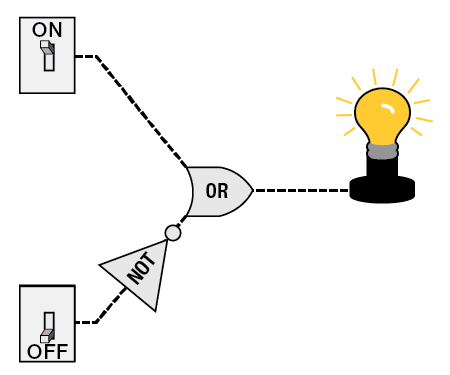
A circuit with two switches leading to an Or gate. The first switch is set to ON. The second switch is set to OFF and leads to a Not gate. The lightbulb is on.
-
For the above diagram, determine the output of the light bulb for each of the four combinations of the switch positions.
-
Top switch on, Bottom switch off:
-
Top switch on, Bottom switch on:
-
Top switch off, Bottom switch on:
-
Top switch off, Bottom switch off:
-
-
Now it's your turn to design some circuits. (Part c. will require some thought, maybe even some trial and error on your part.)
-
Design a circuit with two switches and at least two gates in which the light is on when at least one switch is off.
-
Design a tautology circuit with two switches and at least two gates (that is, the light bulb is always on).
-
Design a circuit with two switches and at least two gates in which the light is on when precisely one switch is on.
-
-
Describe a scenario in which the circuits you designed in Questions and could be used to control something. For example, they could control the switches for the buzzer in a quiz match or spotlights for a concert when certain musicians are on the stage. Explain your scenario in detail, noting what each circuit controls and when it will and won't be activated.